3 D PRINTING
WHAT IS 3D PRINTING?
3D printing, also known as additive manufacturing (AM), are processes used to synthesize a three-dimensional object in which successive layers of material are formed under computer control to create the object.
HOW DOES 3D PRINTER WORKS?
To 3D print an object, a digital model first needs to exist in
a computer. This may be fashioned by hand using a computer
aided design (CAD) application, or some other variety of 3D
modelling software. Alternatively, a digital model may be
created by scanning a real object with a 3D scanner, or
perhaps by taking a scan of something and then tweaking it
with software tools.
However the digital model is created, once it is ready to
be fabricated some additional computer software needs to
slice it up into a great many cross sectional layers only a
fraction of a millimetre thick. These object layers can then
be sent to a 3D printer that will print them out, one on top
of the other, until they are built up into a complete 3D
printed object.
ADVANTAGES OF 3D PRINTING:
Layer by layer production allows for much greater flexibility and creativity in the design
process. No longer do designers have to design for manufacture, but instead they can create a
part that is lighter and stronger by means of better design. Parts can be completely re-designed
so that they are stronger in the areas that they need to be and lighter overall.
3D Printing significantly speeds up the design and prototyping process. There is no problem
with creating one part at a time, and changing the design each time it is produced. Parts can be
created within hours. Bringing the design cycle down to a matter of days or weeks compared
to months. Also, since the price of 3D printers has decreased over the years, some 3D
printers are now within financial reach of the ordinary consumer or small company.
TYPES OF 3D PRINTING:
1. FDM – Fused Deposition Modeling
 Fused Deposition Modeling, is an additive manufacturing technology commonly used for
modeling, prototyping, and production applications.
FDM works on an "additive" principle by laying down material in layers. A plastic filament or
metal wire is unwound from a coil and supplies material to an extrusion nozzle which can turn
the flow on and off. The nozzle is heated to melt the material and can be moved in both
horizontal and vertical directions by a numerically controlled mechanism, directly controlled by
a computer-aided manufacturing (CAM) software package. The model or part is produced by
extruding small beads of thermoplastic material to form layers as the material hardens
immediately after extrusion from the nozzle. Stepper motors or servo motors are typically
employed to move the extrusion head.
FDM, a prominent form of rapid prototyping, is used for prototyping and rapid manufacturing.
Rapid prototyping facilitates iterative testing, and for very short runs, rapid manufacturing can
be a relatively inexpensive alternative.
Fused Deposition Modeling, is an additive manufacturing technology commonly used for
modeling, prototyping, and production applications.
FDM works on an "additive" principle by laying down material in layers. A plastic filament or
metal wire is unwound from a coil and supplies material to an extrusion nozzle which can turn
the flow on and off. The nozzle is heated to melt the material and can be moved in both
horizontal and vertical directions by a numerically controlled mechanism, directly controlled by
a computer-aided manufacturing (CAM) software package. The model or part is produced by
extruding small beads of thermoplastic material to form layers as the material hardens
immediately after extrusion from the nozzle. Stepper motors or servo motors are typically
employed to move the extrusion head.
FDM, a prominent form of rapid prototyping, is used for prototyping and rapid manufacturing.
Rapid prototyping facilitates iterative testing, and for very short runs, rapid manufacturing can
be a relatively inexpensive alternative.
Advantages: Cheaper since uses plastic, more expensive models use a different (water
soluble) material to remove supports completely. Even cheap 3D printers have enough
resolution for many applications.
Disadvantages: Supports leave marks that require removing and sanding. Warping, limited
testing allowed due to Thermo plastic material.
2. SLA – Stereolithography
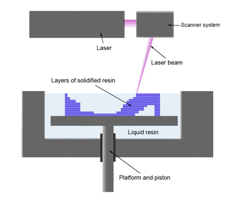 Stereolithography is an additive manufacturing process which employs a vat of liquid
ultraviolet curable photopolymer "resin" and an ultraviolet laser to build parts' layers one at a
time. For each layer, the laser beam traces a cross-section of the part pattern on the surface of
the liquid resin. Exposure to the ultraviolet laser light cures and solidifies the pattern traced on
the resin and joins it to the layer below.
After the pattern has been traced, the SLA's elevator platform descends by a distance equal to
the thickness of a single layer, typically 0.05 mm to 0.15 mm (0.002" to 0.006"). Then, a resinfilled
blade sweeps across the cross section of the part, re-coating it with fresh material. On
this new liquid surface, the subsequent layer pattern is traced, joining the previous layer. A
complete 3-D part is formed by this process. After being built, parts are immersed in a chemical
bath in order to be cleaned of excess resin and are subsequently cured in an ultraviolet oven.
Stereolithography requires the use of supporting structures which serve to attach the part to
the elevator platform, prevent deflection due to gravity and hold the cross sections in place so
that they resist lateral pressure from the re-coater blade. Supports are generated automatically
during the preparation of 3D Computer Aided Design models for use on the stereolithography
machine, although they may be manipulated manually. Supports must be removed from the
finished product manually, unlike in other, less costly, rapid prototyping technologies.
Stereolithography is an additive manufacturing process which employs a vat of liquid
ultraviolet curable photopolymer "resin" and an ultraviolet laser to build parts' layers one at a
time. For each layer, the laser beam traces a cross-section of the part pattern on the surface of
the liquid resin. Exposure to the ultraviolet laser light cures and solidifies the pattern traced on
the resin and joins it to the layer below.
After the pattern has been traced, the SLA's elevator platform descends by a distance equal to
the thickness of a single layer, typically 0.05 mm to 0.15 mm (0.002" to 0.006"). Then, a resinfilled
blade sweeps across the cross section of the part, re-coating it with fresh material. On
this new liquid surface, the subsequent layer pattern is traced, joining the previous layer. A
complete 3-D part is formed by this process. After being built, parts are immersed in a chemical
bath in order to be cleaned of excess resin and are subsequently cured in an ultraviolet oven.
Stereolithography requires the use of supporting structures which serve to attach the part to
the elevator platform, prevent deflection due to gravity and hold the cross sections in place so
that they resist lateral pressure from the re-coater blade. Supports are generated automatically
during the preparation of 3D Computer Aided Design models for use on the stereolithography
machine, although they may be manipulated manually. Supports must be removed from the
finished product manually, unlike in other, less costly, rapid prototyping technologies.
ADVANTAGES:
One of the advantages of stereolithography is its speed; functional parts can be manufactured
within a day. The length of time it takes to produce one particular part depends on the size and
complexity of the project and can last from a few hours to more than a day. Most
stereolithography machines can produce parts with a maximum size of approximately
50×50×60 cm (20"×20"×24") and some, such as the Mammoth stereolithography machine
(which has a build platform of 210×70×80 cm),[7] are capable of producing single parts of more
than 2m in length. Prototypes made by stereolithography are strong enough to
be machined and can be used as master patterns for injection molding, thermoforming, blow
molding, and various metal casting processes.
DISADVANTAGES:
Although stereolithography can produce a wide variety of shapes, it has often been expensive;
the cost of photo-curable resin has long ranged from $80 to $210 per liter, and the cost of
stereolithography machines has ranged from $100,000 to more than $500,000.
3. SLS - Selective laser sintering
 Selective laser sintering is an additive manufacturing technique that uses a high power laser
(for example, a carbon dioxide laser) to fuse small particles of plastic, metal (direct metal laser
sintering), ceramic, or glass powders into a mass that has a desired three-dimensional shape.
The laser selectively fuses powdered material by scanning cross-sections generated from a 3-D
digital description of the part (for example from a CAD file or scan data) on the surface of a
powder bed. After each cross-section is scanned, the powder bed is lowered by one layer
thickness, a new layer of material is applied on top, and the process is repeated until the part is
completed.
Because finished part density depends on peak laser power, rather than laser duration, a SLS
machine typically uses a pulsed laser. The SLS machine preheats the bulk powder material in the
powder bed somewhat below its melting point, to make it easier for the laser to raise the
temperature of the selected regions the rest of the way to the melting point.
Some SLS machines use single-component powder, such as direct metal laser sintering.
However, most SLS machines use two-component powders, typically either coated powder or
a powder mixture. In single-component powders, the laser melts only the outer surface of the
particles (surface melting), fusing the solid non-melted cores to each other and to the previous
layer.
Compared with other methods of additive manufacturing, SLS can produce parts from a
relatively wide range of commercially available powder materials. These include polymers such as nylon (neat, glass-filled, or with other fillers) or polystyrene, metals including steel, titanium,
alloy mixtures, and composites and green sand. The physical process can be full melting, partial
melting, or liquid-phase sintering. Depending on the material, up to 100% density can be
achieved with material properties comparable to those from conventional manufacturing
methods. In many cases large numbers of parts can be packed within the powder bed, allowing
very high productivity.
SLS is performed by machines called SLS systems. SLS technology is in wide use around the
world due to its ability to easily make very complex geometries directly from digital CAD data.
While it began as a way to build prototype parts early in the design cycle, it is increasingly being
used in limited-run manufacturing to produce end-use parts. One less expected and rapidly
growing application of SLS is its use in art.
Selective laser sintering is an additive manufacturing technique that uses a high power laser
(for example, a carbon dioxide laser) to fuse small particles of plastic, metal (direct metal laser
sintering), ceramic, or glass powders into a mass that has a desired three-dimensional shape.
The laser selectively fuses powdered material by scanning cross-sections generated from a 3-D
digital description of the part (for example from a CAD file or scan data) on the surface of a
powder bed. After each cross-section is scanned, the powder bed is lowered by one layer
thickness, a new layer of material is applied on top, and the process is repeated until the part is
completed.
Because finished part density depends on peak laser power, rather than laser duration, a SLS
machine typically uses a pulsed laser. The SLS machine preheats the bulk powder material in the
powder bed somewhat below its melting point, to make it easier for the laser to raise the
temperature of the selected regions the rest of the way to the melting point.
Some SLS machines use single-component powder, such as direct metal laser sintering.
However, most SLS machines use two-component powders, typically either coated powder or
a powder mixture. In single-component powders, the laser melts only the outer surface of the
particles (surface melting), fusing the solid non-melted cores to each other and to the previous
layer.
Compared with other methods of additive manufacturing, SLS can produce parts from a
relatively wide range of commercially available powder materials. These include polymers such as nylon (neat, glass-filled, or with other fillers) or polystyrene, metals including steel, titanium,
alloy mixtures, and composites and green sand. The physical process can be full melting, partial
melting, or liquid-phase sintering. Depending on the material, up to 100% density can be
achieved with material properties comparable to those from conventional manufacturing
methods. In many cases large numbers of parts can be packed within the powder bed, allowing
very high productivity.
SLS is performed by machines called SLS systems. SLS technology is in wide use around the
world due to its ability to easily make very complex geometries directly from digital CAD data.
While it began as a way to build prototype parts early in the design cycle, it is increasingly being
used in limited-run manufacturing to produce end-use parts. One less expected and rapidly
growing application of SLS is its use in art.
ADVANTAGES:
SLS has many benefits over traditional manufacturing techniques. Speed is the most obvious because
no special tooling is required and parts can be built in a matter of hours. Additionally, SLS allows for
more rigorous testing of prototypes. Since SLS can use most alloys, prototypes can now be
functional hardware made out of the same material as production components.
SLS is also one of the few additive manufacturing technologies being used in production. Since the
components are built layer by layer, it is possible to design internal features and passages that could
not be cast or otherwise machined. Complex geometries and assemblies with multiple components
can be simplified to fewer parts with a more cost effective assembly. SLS does not require special
tooling like castings, so it is convenient for short production runs.
NOTE: 1. IF YOU ENJOYED IT PLEASE SUBSCRIBE AND FOLLOW FOR ANOTHER POSTS.
2. IF YOU WANT TO LEARN ABOUT A TOPIC JUST COMMENT THE NAME OF THE TOPIC, I WILL MAKE POST OF THAT TOPIC.